Ethernet cabling refers to the physical wires used to connect computers, routers, and switches within a Local Area Network (LAN). It transmits data as electrical pulses, providing a significantly more stable, secure, and faster internet connection than wireless networks like Wi-Fi. Not all cable is considered equal and there’s quite a bit to consider when you’re deploying low-voltage infrastructure to support common local area networks.
In this post, we’ll scratch the surface and I’ll point out some of the basics to help display the different types of Ethernet cabling. We’ll also lightly touch on how things interconnect using Ethernet cabling. Let’s get started!
Ethernet Cable – Construction, Category, Data Rate, Bandwidth, Distance, and Common Usage
Immediately below is a cut-away image of a Cat5e Ethernet cable. Note the blue protective outer jacket, 4 twisted pairs (8 total conductors) that are twisted to reduce cross-talk of conductor wires, and a ripcord that’s used to slice open the outer jacket of the cable to expose the twisted pairs. The twisted pairs of conductor wires are color-coded: green, white-green / orange, white-orange / blue, white-blue / brown, white-brown. The conductor wires can be solid or stranded core. For what we’re talking about in this post, let’s run with solid core wiring.
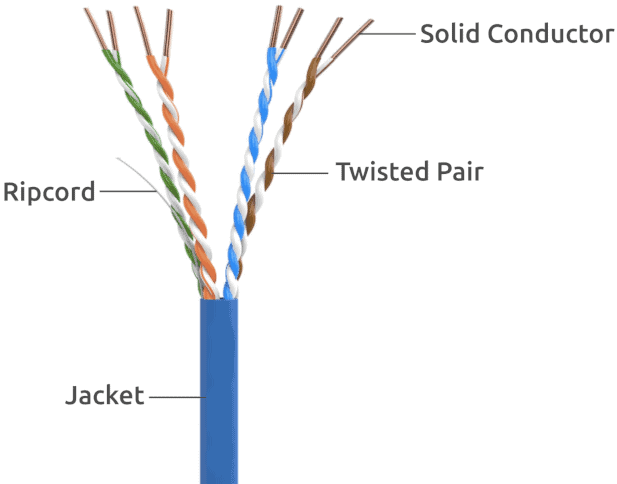
Each conductor wire serves a purpose, as displayed in chart below.
| Wire Pair | Pin Numbers | Primary Function |
|---|---|---|
| Orange/White & Orange | 1 & 2 | Transmit Data: These wires carry outbound data (signals leaving your device). |
| Green/White & Green | 3 & 6 | Receive Data: These wires capture inbound data (signals coming from the internet or other devices). |
| Blue & Blue/White | 4 & 5 | Spare / PoE: In 10/100 Mbps networks, these are spare. In Gigabit+ networks, they are used for data transmission. They are also commonly used for Power over Ethernet (PoE) to supply electrical power to devices like security cameras or VoIP phones. |
| Brown & Brown/White | 7 & 8 | Spare / PoE: Similar to the blue pair, these wires are used for additional data lanes in Gigabit and faster networks and help carry PoE power. |
Below is a reference chart displaying the various types (categories) of network cabling that everyone has most likely run across at some point. You can buy pre-made cables or boxed spools of cabling for larger projects. Every “Category” represents a generation of engineering. As the numbers go up, so do the the specs including tighter wire twists, better insulation, and optimized shielding. All of these improvements aim to reduce crosstalk (noisy signal interference between conductor wires) and try to buck EMI (Electro Magnetic Interference). Less noise allows data to travel at higher frequencies (measured in Megahertz, or MHz). These days, Cat5e and greater are what you’ll most often run into.
| Cable Category Type | Maximum Data Rate | Bandwidth | Maximum Distance | Typical Usage |
|---|---|---|---|---|
| Category 1 | 1 Mbps | 0.4 MHz | Telephone and modem lines | |
| Category 2 | 4 Mbps | 4 MHz | LocalTalk & Telephone | |
| Category 3 | 10 Mbps | 16 MHz | 100 m (328 ft.) | 10BaseT Ethernet |
| Category 4 | 16 Mbps | 20 MHz | 100 m (328 ft.) | Token Ring |
| Category 5 | 100 Mbps | 100 MHz | 100 m (328 ft.) | 100BaseT Ethernet |
| Category 5e | 1 Gbps | 100 MHz | 100 m (328 ft.) | 100BaseT Ethernet, residential homes |
| Category 6 | 1 Gbps | 250 MHz | 100 m (328 ft.) 10Gb at 37 m (121 ft.) | Gigabit Ethernet, commercial buildings |
| Category 6a | 10 Gbps | 500 MHz | 100 m (328 ft.) | Gigabit Ethernet in data centers and commercial buildings |
| Category 7 | 10 Gbps | 600 MHz | 100 m (328 ft.) | 10 Gbps Core Infrastructure |
| Category 7a | 10 Gbps | 1000 MHz | 100 m (328 ft.) 40Gb at 50 m (164 ft.) | 10 Gbps Core Infrastructure |
| Category 8 | 25 Gbps (Cat8.1) 40 Gbps (Cat8.2) | 2000 MHz | 30 m (98 ft.) | 25 Gbps/40 Gbps Core Infrastructure |
Cable Shielding
The primary purpose of shielding in Ethernet cables is to protect data transmissions from Electromagnetic Interference (EMI) and Radio Frequency Interference (RFI). It ensures signal integrity and maintains high-speed performance in environments with heavy electronic activity. You would choose the cabling for your specific application. For example, if you install network cabling to a manufacturing environment that has a potential for a lot of interference, you’d want cabling with the appropriate shielding. Defer to your low-voltage professionals for direction on what to use for your application.
| ISO/IEC Designation | Common Abbreviation | Shielding – Conductor | Shielding – Cable |
|---|---|---|---|
| U/UTP | UTP or TPP | None | None |
| F/UTP | FTP or STP | Foil | None |
| S/UTP | STP | Braiding | None |
| SF/UTP | SFTP or STP | Braiding & Foil | None |
| U/FTP | STP | None | Foil |
| F/FTP | FFTP | Foil | Foil |
| S/FTP | SFTP | Braiding | Foil |
| SF/FTP | SFTP or SSTP | Braiding & Foil | Foil |
| S/STP | SSTP | Braiding | Braiding |
In my last paragraph, I mentioned low voltage professionals. Find a good one and work with them when planning cabling projects. Up to this point, we’ve been zoning in on just the physical cabling and its characteristics. As you’re probably starting to realize, there’s a little more to this than some may think. For instance, there are low-voltage building codes, local codes and industry standards, and safety measures to consider. There are specific kinds of Ethernet cabling that are Plenum Rated. A plenum rated Ethernet cable is a networking cable specially designed with a fire-retardant jacket. It emits very little smoke and few toxic fumes when burned. You must use plenum rated cables when running wires through plenum spaces which are the hidden air-handling areas of a building such as the space above drop ceilings or below raised floors. There’s also a requirement to use fire stop sealant when passing cabling through fireproof walls. Fire stopping is required whenever cables penetrate a fire-rated wall or floor (such as firewalls, smoke barriers, or shaft enclosures). Its purpose is to seal the openings around the cables to maintain the structure’s original fire-resistance rating and prevent the spread of flames, smoke, and toxic gases. Again, you should always consult with a professional.
Moving on from the network cabling, we’ll look at the other components that you’d commonly find on an Ethernet network.
RJ45 Modular Cable Ends
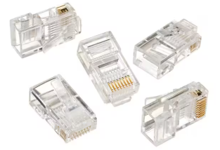
The RJ45 Modular Plug (cable end) is the plastic, clip-like contraption that crimps on to each end of an Ethernet cable and ultimately inserts into a switch port, network device, patch panel, or wall jack. They look like the image below and require special tools to make the crimp connection. I have hand made and crimped a LOT of cables and I would challenge anyone to make one faster than me!
This is what an RJ45 Modular Plug looks like:
This is what a RJ45 Crimp Tool looks like:

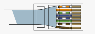
To crimp a cable end on to a network cable, you strip back the outer jacket to expose the 4 wire pairs. You untwist each pair as little as possible and line up the 8 conductors in the correct order (we will cover that next). At this time, it’s important to trim the wires down so that they are as short as reasonably possible to allow them to slip into the cable end slots. Make sure that the cable jacket is contained inside the RJ45 cable end. Afterwards, you grab your crimp tool and crimp the connector so that it’s permanently affixed to the network cable. This is what the finished product should look like.
Wiring Pin-Out
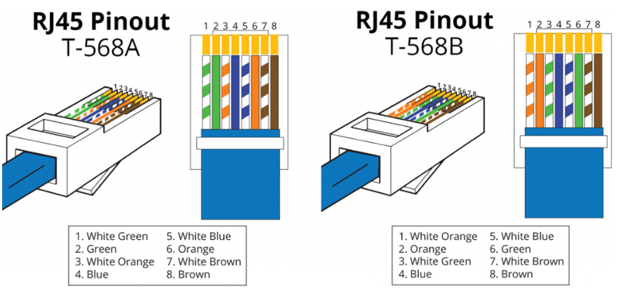
T568A and T568B are the two standards. The main difference between T56A and T56B is the color order of green and orange pairs. Most commonly, the RJ45 Modular Plugs are wired the same exact way on each end of a cable and this is known as a “straight-through” cable. Some applications call for a “cross-over” cable. This simply means that one side of the cable is wired in T56A and the other in T56B.
Patch Panels
Ethernet Patch Panels are commonly found in MDF (Main Distribution Frame) and IDF (Intermediate Distribution Frame) rooms or closets. An Ethernet patch panel organizes and centralizes multiple network cable drops in a structured cabling system. Patch Panels provide a clean, mounted termination point for cable runs that originate from wall jacks and other places. From the Patch Panels in your network racks, you then “patch” them into a network switch. Pre-made Patch Cables are commonly used to link the ports on the front of the patch panel to nearby Ethernet switch ports. Immediately below is a high level view on where Patch Panels fit between your PC NIC and the destination Ethernet network switch.
Your PC NIC <— Ethernet Patch Cable —> Wall Jack — Hidden/Fixed Ethernet Cable Run —- Patch Panel <— Ethernet Patch Cable —> Ethernet Network Switch
Below is what a common Ethernet Patch Panel looks like. The front view is on top and the rear view is on the bottom.
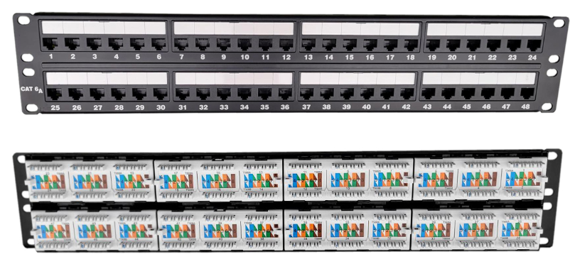
To terminate an Ethernet cable run to the rear of the patch panel, and to the rear of your Ethernet wall jack, you require a special tool called an Ethernet Punch Down Tool. The tool is used to neatly shove the Ethernet cable conductor wires into their color-coded slots using the T56A or T56B pin-out standards. You can see the color-coded pin arrangement diagram on the rear view of the patch panel displayed above. As you push the conductor wires into the corresponding colored slot of the patch panel by putting pressure on the tool, the tool will ultimately “punch down” and trim off excess wiring leaving a neat wire termination behind; and not something that looks like a barbaric caveman installed it. Below is what a punch down tool looks like. Orient the tool the right way. Some lessons are worth learning the hard way so you’ll know what I mean if you don’t!

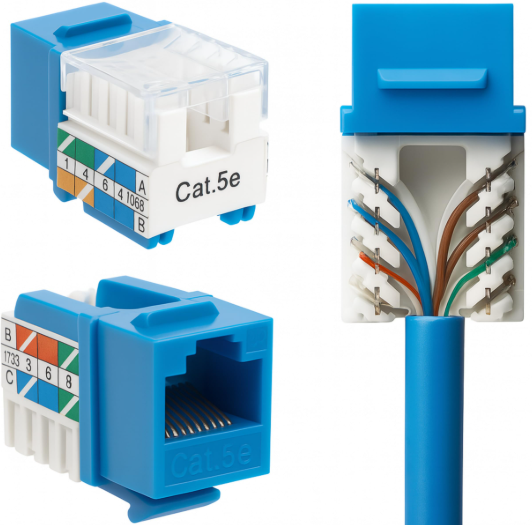
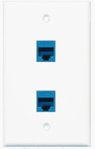
I briefly mentioned that Ethernet cabling is punched down to the rear side of a wall jack. On the wall jack side, the component the cabling is punched down to is often called a RJ45 Keystone Jack or RJ45 Quick Port. For those interested, this is the behind the scenes view of what’s going on behind the wall jack faceplate. The general procedure is to strip back the outer jacket from the cabling, line up the cable pairs to the Keystone Jack using the T56A or T56B standard, and then punching down the conductor wiring to the Keystone Jack. Then you simply snap the Keystone Jack into the faceplate and mount the faceplate to the wall. Below are pictures of a Keystone Jack with conductor wiring punched down to the component. Additionally, a fully assembled 2-port face plate with 2 RJ45 Keystone Jacks mounted to it is displayed below.
Always use a label maker and label the faceplate so that you can identify it and know where the other end is. The information on the faceplate label needs to align to the patch panel port number on the other end. Use a naming convention like MDF1-P1-22. The MDF1 part identifies that this cable run goes to the MDF1 room. P1 identifies Patch Panel 1 in the MDF1 room. The number 22 lines up with port 22 on Patch Panel 1 in the MDF1 room. You get it.
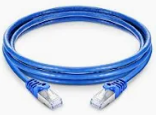
An Ethernet Patch Cable is commonly a shorter (3ft, 7ft, 14ft) cable that’s purchased and ready to use with RJ45 modular ends preinstalled. The cable connects a PC network interface card to the wall port, on the office side of the cable run. Back in the MDF or IDF, where the patch panels are located, another patch cable is used to link the patch panel port to a nearby switch. Patch cables look like this:
In the end, if all the moons align and you’ve punched down and crimped everything right, you’ll be rewarded with the glorious green link light on both the computer NIC and the switch port! Job well done. If you don’t get a link light, you’ll need to get a cable tester and perform additional troubleshooting; which really leads me to my final point before wrapping up this post.
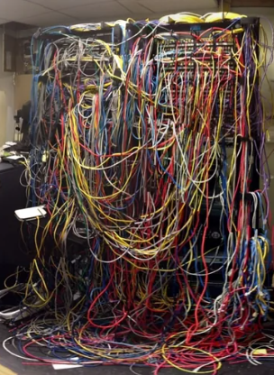
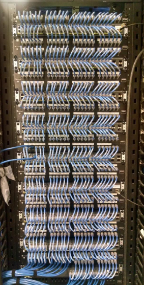
Earlier in this post, I jokingly referenced something that “looks like a barbaric caveman installed it”. I want to elaborate on this. For those of you who know me, you’ll probably chuckle and probably don’t need to read too much further. For those of you who don’t know me, I am self-admittingly “that guy” when it comes to maintaining cabling order. I’ll make a few final points about my take on this and then ask you to look at the 2 photos below.
- Do it once and do it right, or don’t do it at all
- Be kind to your future self, set yourself up for future success when troubleshooting or replacing network gear
- Use the same color cabling for similar use cases
- Always route cabling through rack channels, cable runners, organizers, and cable trays
- Don’t run cabling across the front of racks or lay cabling across ceiling tiles and lighting ballasts. Keep cable runs shorter than their maximum distance.
Ask yourself, “In which environment would I want to troubleshoot a problem or replace a failed switch in?”. The choice is yours.